Designing a Field Drip Zone around Crop and Water Inputs
Published
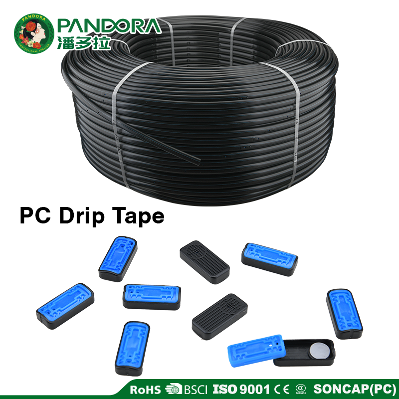
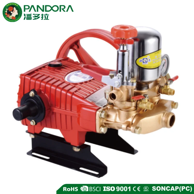
Design a field drip zone by working from the crop rows back to the water source. First decide how many laterals will run together and how much water their emitters need. Then check whether the source can supply that flow while holding enough pressure at the most demanding lateral. A tape specification and a pump nameplate are useful inputs, but the zone works only when the two match under actual operating conditions.
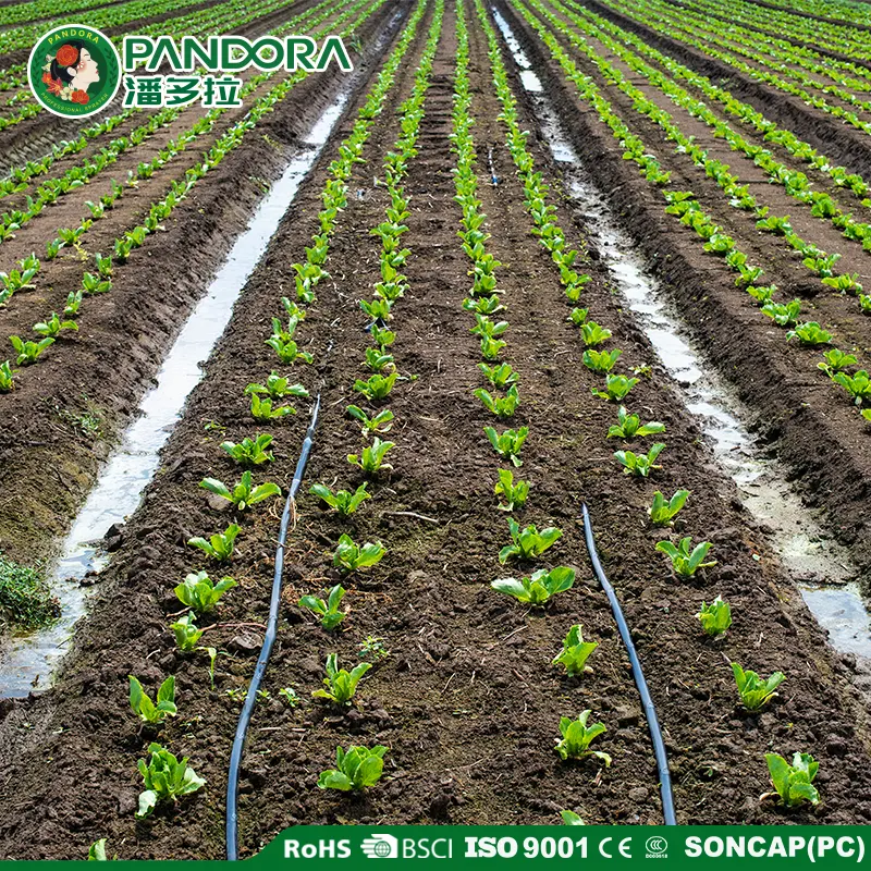
Map the Rows and the Wetting Target
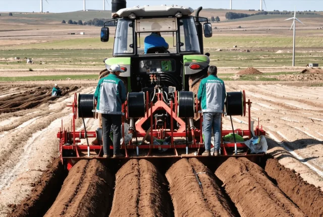
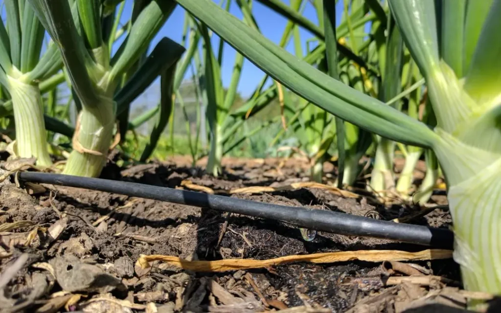
Draw the field as it will be planted. Mark row lengths, bed widths, the number of crop rows on each bed, the headland, and the high and low points. Show where the header can run and where a crew can reach the ends to flush the tape. Record whether the tape is on the surface, under mulch or installed by a machine. These choices affect the number of laterals, connection locations and the roll format you can order.
Decide what wetted root zone the crop needs, then check it in representative soil. Two rows of the same length may need different layouts when one sits on coarse soil and the other holds water closer to the surface. Emitter spacing along a tape and lateral spacing across a bed are separate decisions. Penn State Extension’s commercial vegetable irrigation guide explains how soil, outlet spacing and total flow interact. Use a test section to confirm wetting depth and width before buying rolls for the whole field.
Calculate the Flow That Must Run at One Time
Count the laterals served by one valve and estimate the number of active emitters on each lateral. Multiply that count by the emitter’s stated flow at the appropriate reference pressure. If the supplier gives flow per 100 feet or per 100 meters, use that basis directly. Keep the rating pressure with the value so two quotes can be compared on a consistent basis.
| Input | Example | What to verify |
|---|---|---|
| Active rows | 12 laterals of 75 m | Which rows run together after the last valve opens |
| Outlet spacing | 0.30 m | Emitter pitch on the ordered roll and the end cut position |
| Active outlets | Approximately 3,000 | Use measured row lengths where beds differ |
| Nominal emitter flow | 1.0 L/h per outlet at the stated rating pressure | Confirm the actual SKU curve and test pressure |
| Nominal operation flow | About 3,000 L/h, or 3.0 m³/h | Check source delivery and any separately planned flushing |
In this example, 75 ÷ 0.30 gives about 250 emitters per lateral, and 250 × 12 × 1.0 gives about 3,000 L/h. Moving to 0.20 m spacing at the same nominal rate would bring the calculation to approximately 4,500 L/h. The change can affect the header, the filter and the pump even if the crop acreage stays the same. If the source is short on flow, evaluate smaller valve groups before choosing a lower-flow emitter. Smaller zones change the operating schedule and available irrigation hours.
Check Pressure with the Zone Flowing
Record the pressure that remains when the source delivers the expected flow. A gauge reading with the valves closed gives static pressure. For the specification, record operating pressure upstream and downstream of the filter and at the zone entrance. Your designer can then allow for header and lateral friction, elevation and changes in filter condition. A rise in elevation generally reduces pressure. A descent can increase it and may put low points above the tape’s limit even when distant high points are still short of pressure.
Keep separate values for source pressure, tape inlet pressure and the usable pressure range on the model sheet. Request a length or pressure table for the ordered diameter, wall, emitter spacing and discharge. It is especially helpful if the supplier identifies the slope and permissible emitter variation used to derive its length figure. Treat a quoted maximum lateral length as a result for that set of assumptions.
Choose Filters and Fittings with the Roll
Describe the source water honestly. A well and an open reservoir can require different treatment even if both have the same measured flow. Provide any known sediment, organic load or water test results. Size filtration for the water and emitter together, then include a means of reading the pressure on both sides of the filter. Confirm the opening in microns when comparing screen ratings. For connections, specify the header material and takeoff interface as well as the diameter and wall of the tape. Check that ends can be opened for flushing and then closed securely. University of Minnesota Extension’s irrigation setups provide examples of how these parts fit into production systems.
Commission One Block before Ordering the Rest
Choose a pilot that includes the longest lateral or a meaningful elevation change. Include a typical row as a comparison. Record the tape model, pressure regulator, filter, water source and length before opening the zone. Flush the header and laterals according to the supplied instructions. Once flow and pressure stabilize, note readings at the zone entrance and at representative laterals. Observe the starts and ends for leaks. Collect outlet water over the same timed interval at the head, middle and tail. Repeat at another lateral if the first comparison is irregular.
Check wetting in the soil after the planned run. Similar collected emitter volumes can still produce different wetting where soil changes. Use these results to separate an equipment question from a crop management decision. A repeatable flow and pressure check supports the purchase specification. Irrigation duration, crop response and harvest outcomes also depend on conditions beyond the equipment. If the zone performs differently from the plan, change one variable at a time and write the revised configuration back into the order.
Send a Quote Request That Can Be Priced
For an importer buying for several growers, ask for a base kit and keep site-dependent parts listed separately. Rolls and matched end closures may stay consistent, while the header, valve and filtration sizes change with the water source and the number of rows run together. Give each pilot kit a revision code and note what the crew changed. When a distributor repeats the order six months later, that code should lead back to the approved layout and replacement parts.
Send a field sketch with the row schedule, slope and water source. Add measured flow and pressure under load, tape diameter and wall, emitter spacing, rated flow and pressure, intended roll length, installation method and estimated quantities. List the filters, valves, takeoffs, ends and spares that should be included, with the destination and delivery window. Confirm who is responsible for hydraulic sizing and installation before you approve the equipment. Splitting these details by zone helps the supplier show which parts of the quote use the same SKU and which need a separate line.
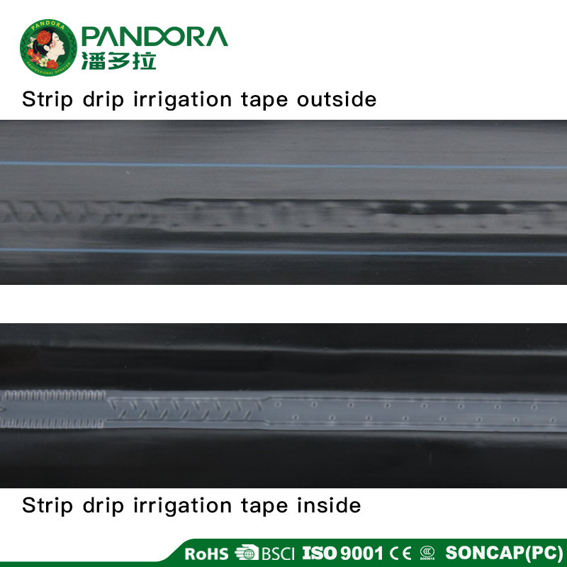
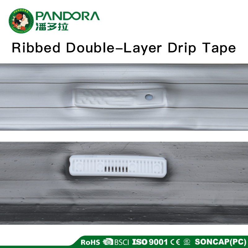
Compare the agricultural drip irrigation range and use the inlaid patch drip tape model sheet as an example of how size, wall and spacing are described. Send PANDORA the field and water-source details to discuss test rolls and the equipment list for the pilot.
Turn Insight Into Action
Need Product Recommendations for Your Market?
Share your target crop, product category, order quantity, packaging needs, and OEM/ODM goals. PANDORA can help prepare a practical sourcing route.